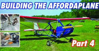
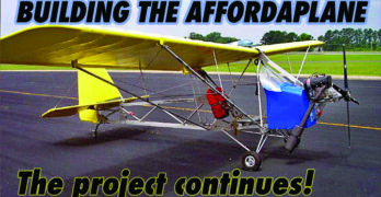
With this, the last chapter of the Affordaplane build, I will describe how an engine mount was created to complete the last major step. As a quick recap of the previous chapters in this series, I was attempting to plans build a legal ultralight using common tools and store-purchased materials. For example: No welding allowed! So, now the biggest challenge confronting me was creating an engine mount needed for the engine installation.
First, what engine should be used in this project? This decision could not be made until we were nearly finished with the entire project. Why? The choice of engine is determined by how much weight remains after deducting the aircraft’s total weight from the 254-pound limit imposed by the FAA ultralight regulations. With the wings and tail attached to the fuselage, I weighed the entire structure. Without an engine, the scales read very close to 200 pounds.
Building the Affordaplane, Part 3
In the previous installment, I described construction details for the fuselage section of the Affordaplane ultralight project. Now let’s look at construction of the empennage and wing assemblies. Remember, this is a plans-only type of build using off-the-shelf materials and tools intended for a novice builder. Keep this objective in mind when reviewing the construction and design details. A complete free video series on YouTube shows each step of this construction.
The components of the empennage (rudder, elevator, vertical and horizontal stabilizers) are all formed from 1-inch 6061-T6 aluminum tubing. These tubes must be bent into their respective shapes, matching template patterns drawn on your workbench. (Use some craft paper for this!) What is the easiest way to form these simple bends? I found that using an electrician’s conduit bender did the job nicely. With a little practice, each tube was formed to the proper shape and then fitted with a gusset to join its ends.


